News
INFORMATIONinquiry
+86-021-62800366 Glory Engineering Shanghai Co.,Ltd
Tel:15021911896
Fax:+86-021-62800366
Email:romaxsecu@gmail.com
Tel:15021911896
Fax:+86-021-62800366
Email:romaxsecu@gmail.com
NGP Motor
NGP lifting motor YG/YGP
NGP lifting motor YG/YGP
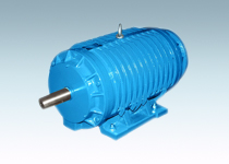
I plant production YG series (H100-225) is based on the JG2 series, with reference to ABB's RM series improved design of a new generation of high reliability roller motor , it has a small size, light weight, good performance, the use of Reliable, easy maintenance and so on. And increase the bearing grease and then re-supply device, using a high temperature lubricant, to strengthen the mechanical strength, the comprehensive technical and economic indicators to the domestic advanced level, and ABB RM series roller motor quite.
YG series of roller motor can be in the frequent start, forward and reverse, reverse braking and other impact load and high temperature, dusty environment under the harsh conditions of continuous work, with high overload capacity for rolling mill work roller and transport Of the special motor, can also be applied to other mechanical equipment.
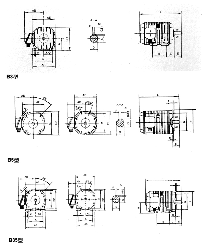
YG series roller motor rated voltage of 380V, rated frequency of 50Hz, Y connection, insulation class F, H pole, protection class IP54, installation type B3, B5, B35, cooling method for the IC0041, the motor can be full pressure Direct start.
Under the control of VVVF, YG series roller motor can work normally in the range of 5-70Hz, but its main performance index is different from the guarantee value stipulated in the sample.
YG series of roller motor is divided into two types:
YGa is mainly used for work roller, working for S5 40%.
YGb is mainly used for conveying roller, working system for S1.
I plant production YG series (H100-225) is based on the JG2 series, with reference to ABB's RM series improved design of a new generation of high reliability roller motor , it has a small size, light weight, good performance, the use of Reliable, easy maintenance and so on. And increase the bearing grease and then re-supply device, using a high temperature lubricant, to strengthen the mechanical strength, the comprehensive technical and economic indicators to the domestic advanced level, and ABB RM series roller motor quite.
YG series of roller motor can be in the frequent start, forward and reverse, reverse braking and other impact load and high temperature, dusty environment under the harsh conditions of continuous work, with high overload capacity for rolling mill work roller and transport Of the special motor, can also be applied to other mechanical equipment.
YG series roller motor rated voltage of 380V, rated frequency of 50Hz, Y connection, insulation class F, H pole, protection class IP54, installation type B3, B5, B35, cooling method for the IC0041, the motor can be full pressure Direct start.
Under the control of VVVF, YG series roller motor can work normally in the range of 5-70Hz, but its main performance index is different from the guarantee value stipulated in the sample.
YG series of roller motor is divided into two types:
YGa is mainly used for work roller, working for S5 40%.
YGb is mainly used for conveying roller, working system for S1.
| The main technical parameters | ||||||||||||||||||||||||||||||||||||||||||||||||||||||||||||||||||||||||||||||||||||||||||||||||||||||||||||||||||||||||||||||||||||||||||||||||||||||||||||||||||||||||||||||||||||||||||||||||||||||||||||||||||||||||||||||||||||||||||||||||||||||||||||||||||||||||||||||||||||||||||||||||||||||||||||||||||||||||||||||||||||||||||||||||||||||||||||||||||||||||||||||||||||||||||||||||||||||||||||||||||||||||||||||||||||||||||||||||||||||||||||||||||||||||||||||||||||||||||
|
||||||||||||||||||||||||||||||||||||||||||||||||||||||||||||||||||||||||||||||||||||||||||||||||||||||||||||||||||||||||||||||||||||||||||||||||||||||||||||||||||||||||||||||||||||||||||||||||||||||||||||||||||||||||||||||||||||||||||||||||||||||||||||||||||||||||||||||||||||||||||||||||||||||||||||||||||||||||||||||||||||||||||||||||||||||||||||||||||||||||||||||||||||||||||||||||||||||||||||||||||||||||||||||||||||||||||||||||||||||||||||||||||||||||||||||||||||||||||
|
||||||||||||||||||||||||||||||||||||||||||||||||||||||||||||||||||||||||||||||||||||||||||||||||||||||||||||||||||||||||||||||||||||||||||||||||||||||||||||||||||||||||||||||||||||||||||||||||||||||||||||||||||||||||||||||||||||||||||||||||||||||||||||||||||||||||||||||||||||||||||||||||||||||||||||||||||||||||||||||||||||||||||||||||||||||||||||||||||||||||||||||||||||||||||||||||||||||||||||||||||||||||||||||||||||||||||||||||